- Fuel-Injection System is vital to the working and performance of CI engine
- This system serves the purpose of initiating and controlling the combustion to meet the demand requirements
- Fuel is injected into combustion chamber towards the end of compression.
- It is atomized as it enters under high velocity and the droplets get vaporized to form a fuel-air mixture.
Functional Requirements of an Injection System:
The following requirements must be met by the Fuel Injection (FI) System:
- Accurate metering of fuel injected per cycle to meet changing demand of speed & load.
- Precise timing of fuel injection in the cycle to ensure performance; power, fuel economy, emissions.
- Proper control of rate of injection to achieve desired heat release during combustion without knocking.
- Proper atomization of fuel into fine droplets
- Proper spray pattern to ensure rapid mixing of fuel & air
- Uniform distribution of fuel droplets throughout the combustion chamber.
- To supply equal quantities of metered fuel to all cylinders in case of multi cylinder engines.
- No lag during beginning and end of injection to eliminate dribbling of fuel droplets into the cylinder.
Functional objectives of Fuel Injection System:
The functional objectives for fuel injection systems such as:
- Power output
- Fuel efficiency
- Emissions performance
- Running on alternative fuel
- Reliability
- Drivability and smooth operation
- Initial cost
- Maintenance cost
- Diagnostic capability
- Range of environmental operation and Engine Tuning
FI Systems Components:

- Fuel tank is to store the fuel.
- Fuel filters to prevent dust and abrasive particles from entering the pump & injectors to reduce wear & tear of components.
- Fuel feed pump to supply fuel from fuel tank to FI system.
- Injection pump to meter and pressurize the fuel for injection.
- Governor to ensure that the amount of fuel injected is in accordance with variation of load .
- Injector to take the fuel from the pump and distribute it in the combustion chamber by atomizing it into fine droplets.
Fuel pump:
- Plunger which is driven by a cam and tappet mechanism at the bottom.
- Barrel in which plunger reciprocates.
- There is a rectangular vertical groove in the plunger which extends from top to another helical groove. The delivery valve which lift off its seat under the liquid fuel pressure and the spring force.
- The fuel pump is connected to fuel atomizer through the passage to spill and supply ports.
- When the plunger is at its bottom stroke the ports spill port and supply port are uncovered oil from low pressure pump after being filtered is forced into the barrel.
- When the plunger moves up due to cam and tappet mechanism, both ports are closed and with further upward movement of plunger the fuel gets compressed.
- The high pressure thus developed lifts the delivery valve off its seats and fuel flows to atomizer through the passage.
- With further rise of plunger, at a certain moment, the spill port is connected to the fuel in the upper part of plunger through the rectangular vertical groove.
- As a result of which a sudden drop in pressure occurs and the delivery valve falls back and occupies its seat against the spring force.
- The plunger is rotated by a rack which is moved in or out by the governor.
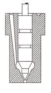
Fuel Injector:
- It consists of nozzle valve fitted in the nozzle body.
- The nozzle valve is held on its seat by a spring which exerts pressure through the spindle.
- Adjusting screw by which the nozzle valve lift can be adjusted.
- Usually the nozzle valve is set to lift at 135 to 170 bar pressure.

- Feeling pin which indicates whether valve is working properly or not.
- The fuel under pressure from the fuel pump enters to the injector through the passage B and C and lift the nozzle valve.
- The fuel travels down nozzle and injected into the engine cylinder in the from of fine spray.
- Then the pressure of the oil falls, the nozzle valve occupies its seat under the spring force and fuel supply is cut off.
- Any leakage of fuel is accumulated above the valve is led to the fuel tank through the passage A. Leakage occurs when the nozzle valve is worn out.
Injector Nozzle:
- The main requirement of an injector nozzle are to inject fuel at a sufficiently high pressure so that fuel enters the cylinder with a high velocity.
- The nozzle are classified as:
- Single hole nozzle
- Multi hole nozzle
- Circumferential nozzle
- Pintle nozzle
- Pintaux nozzle
Single Hole nozzle
- This is used in open combustion chamber.
- It consists of a single hole bored centrally through the nozzle body and closed by the needle valve.
- The size of the hole is usually larger than 0.2mm.
- Its spray cone angle varies from 5 to 15°.
Multi Hole nozzle
- It mixes the fuel with air properly even with slow air movement.
- The number of holes varies from 4 to 18.

- The hole diameter lies between 0.25 to 0.35 mm & Hole angle lies between 20 to 45°.
- Usually the holes are drilled symmetrically but many times they are unsymmetrical to meet certain specific requirements in combustion chamber.
Circumferential Hole nozzle
- The injected fuel particles tend to be projected in the form of plane, with wide angle cone.
- The purpose of which is to obtain as large an area of fuel spray as possible to come into contact with the air in the combustion chamber.

Pintle nozzle
- The stem of nozzle valve is extended to form a pin or pintle which protrudes through the mouth of the nozzle body.
- It may be cylindrical or conical shape, The spray core angle is generally 60°.

- When the valve lift, the pintle partially blocks the orifice and thus does not all the pressure drop to be greater.
- As lift of the valve increases the entire orifice is uncovered and full area for flow is available
Advantages
- It is a self cleaning type
- It avoids weak injection & dribbling.
- It result in good atomization.
Disadvantages
- Distribution & penetration poor
Pintaux nozzle
- In order to Improve cold starting performance without any detrimental effect on efficiency a Pintaux nozzle is used.
- It has auxiliary hole drilled in the nozzle body.

- It injects a small amount of fuel through additional hole(Pilot injection) in the upstream slightly before the main injection.
- The needle valve does not lift fully at low speed and most of the fuel is injected through the auxiliary hole, giving good cold starting performance.
Classification of Fuel Injection System :
Solid injection systems can be classified into
- Individual pump system
- Unit Injector system
- Common rail system
- Distributor system
Common Rail Injection System :
- In the common rail system as shown a multi cylinder high pressure pump is used to supply the fuel at a high pressure to a common rail or header.
- The high pressure in the common rail forces the fuel to each of the nozzle located in the cylinders.

- The pressure in this common rail is kept constant with the help of a high pressure relief valve.
- A metered quantity of fuel is supplied to each cylinder through the nozzle by operating the respective fuel injection valve with the help of cam mechanism driven by the crankshaft of the engine.
*******Thanks*******
Comments
Post a Comment