- Ignition system is a system in an internal combustion engine that produces the spark to ignite the mixture of fuel and air.
- It includes the battery, ignition coil, distributor, spark plugs, and associated switches and wiring.
- It is a part of the electrical system which carries the electrical current to a current plug.
- It gives the spark to ignite the air-fuel mixture at the correct time
Ignition Function:
- It produces 30,000 volt spark across spark plug
- It Distributes high voltage spark to each spark plug in correct sequence
- Time of the spark occurs when piston is near to top dead center
- Spark timing varies with load, speed, and other conditions
Basic Ignition System:
The components in ignition system are as follow:
- Battery,
- Switch ignition distributor
- Ignition coil
- Spark plugs and
- Necessary wiring
Ignition System types:
- A battery of 12 volts is generally employed. However, a very high voltage surge (of about 25,000 volts in modern engines) is required for ignition purposes.
- The actual voltage at which the spark occurs is called breakdown voltage.
- Actual voltage at spark occur is depends upon following factors
- The Spark gap
- Polarity
- condition of plug electrodes
- Condition of plug insulation
- Moisture on the distributor cap and spark plugs
- Pressure, temperature
- Type of mixture in the combustion chamber.
- There are 3 types of ignition system as follow:
- Battery ignition system ( coil ignition)
- Magneto ignition system
- Electronic ignition system
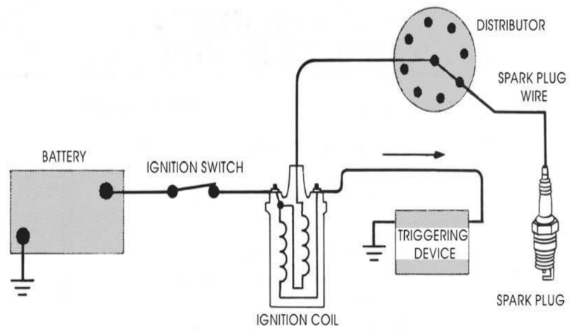
Battery Ignition System :
The figure shows the battery ignition system for a 4 cylinder engine.

- A battery of 12 volts is generally employed.
- There are two basic circuits in the system primary and secondary circuits.
- The primary circuit consist of the battery, ammeter, ignition switch, primary coil winding, capacitor, and breaker points.
The function of these components are :
- Battery – Provides the power to run the system
- Ignition switch – allows the driver to turn the system on and off
- Primary coil – produces the magnetic field to create the high voltage in the secondary coil.
- Breaker points – a mechanical switch that acts as the triggering mechanism
- Capacitor – protects the points from burning out
- The Secondary circuit converts magnetic induction into high voltage electricity to jump across the spark plug gap, firing the mixture at the right time. The function of the components are:
- secondary coil – the part of the coil that creates the high voltage electricity.
- Rotor – spin around on the top of the distributor shaft, and distributes the spark to the right spark plug.
- spark plug – Take the electricity from the wires and give it an air gap in the combustion chamber to jump across to light the mixture.
Producing spark:
- The ignition system consists of two separate but related circuits: the low-voltage primary circuit and the high voltage secondary circuit.
- The ignition coil has two windings: The primary winding of a few hundred turns of heavy wire is part of the primary circuit and The secondary winding of many thousand turns of fine wire is part of the secondary circuit.
- When the ignition key is on and the contact points closed, current flows through the primary winding.
- This produces a magnetic field around the primary winding.
- When the contact points open, current flow stops and magnetic field collapses.
- As it collapses, it cuts across the thousands of turns of wire in the coil secondary winding.
- This produces a voltage in each turn. These add together to produce the high voltage delivered through the secondary circuit to the spark plug.
- The battery ignition system has massive use in cars, light trucks, buses etc.
Magneto Ignition System:
- It has the same principle of working as that of the battery ignition system.
- In this, no battery is required, as the magneto acts as its own generator.
- The working principle of the this ignition System is similar to the working principle of coil or battery ignition system except that in it magneto is used to produce energy but not the battery.
- When engine in the system starts it help magneto to rotate and thereby producing the energy in the form of high voltage.

- The one end of the magneto is grounded through contact breaker and ignition capacitor is connected to it parallel.
- The contact breaker is regulated by the cam and when the breaker is open, current flows through the condenser and charges it.
- As the condenser is acting like a charger now, the primary current flow is reduced thereby reducing the overall magnetic field generated in the system.
- This increases the voltage in the condenser.
- This increased high voltage in the condenser will act as an EMF thereby producing the spark at the right spark plug through the distributor.
Electronic Ignition System:
- The conventional electro-mechanical ignition system uses mechanical contact breakers.
Though it is very simple, it suffers from certain limitation
as follows :
- The contact breaker points handle the heavy current. This resulting in burn out of contact points
- At higher speeds, the make or break of contact may not be timed.
- At higher speeds, the spark strength may be reduced.

- When the driver switch ON the ignition switch the current starts flowing from the battery through the ignition switch to the coil primary winding.
- Which in turn starts the armature pick up coil to receive and send the voltages signals from the armature to the ignition module.
- When the tooth of the rotating reluctor comes in front of the pickup coil, the voltage signal from pickup coil is sent to the electronics module which in turn senses the signals & steps the current to flow form primary coil.
- When the tooth of the rotating reluctor goes away from the pickup coil, the change in voltage signal is sent by pickup coil to the ignition module & a timing circuit inside ignition module turns ON the current flow.
- A magnetic field is generated in the ignition coil due to this continuous make & break of the circuit.
- Which induced an EMF in secondary winding which increases the voltage upto 50,000 volts. The high voltage is them sent to the distributor, which has the rotating rotor & distributor points which is set according to the ignition timing.
- When the rotor comes in front of any of the distributor points the jumping of the voltage through the air gap from the rotor to the distributor point take place which is then sent to the adjacent spark plug.
Ignition Timing:
Ignition timing is the correct instant for the introduction of spark near the end of compression stroke in a cycle.
Important factor which affect ignition timings are:
- Compression ratio
- Engine speed
- Mixture strength
- Combustion chamber design
- Throttle opening
- Engine temperature
- Type of fuel
*******Thanks*******
Comments
Post a Comment