Clutch is a mechanical device that facilitates transmission of power and motion from one component (the driving member) to another (the driven member) when engaged, with a provision for disengagement whenever required.
Function of Clutch:
- It can be disengaged. This allows engine cranking and permits the engine to run without delivering power to the transmission.
- While disengaging, it permits the driver to shift the transmission into various gear according to operating condition.
- While engaging, the clutch slips momentarily. this provides smooth engagement and lessens the shock on gears, shaft and other parts of automobile.
- While engaging, the clutch transmits the power to the wheel without slipping, in ideal condition.
Main Parts of Clutch:
These are known as the
principle parts of the clutch.
• Driving Member
• Driven Member
• Operating Member
Driving Member:
Driving member has a flywheel
which is mounted on the engine crankshaft. A disc is bolted to flywheel which
is known as pressure plate or driving disc.
Driven Member:
The driven member is a disc called clutch plate. This plate can slide freely to and fro on the clutch shaft.
Operating Member:
The operating member consists of a pedal or lever which can be pressed to disengage the driving and driven plate.

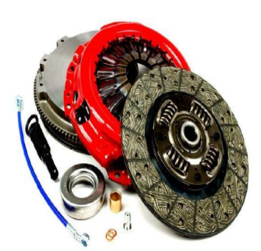
Components of Clutch:
The main component parts of a clutch are:
Driven plate- sometimes referred to as the clutch, Centre or friction plate.
Pressure plate- which comes complete with the clutch cover, springs or diaphragm to provide the force to press the surfaces together.
Release
bearing - which provides the bearing surface which, when the driver
operates the clutch pedal, disconnects the drive between the engine and the
gear box.
Flywheel
- the
main driving member of the clutch.

Type
of Clutch:
Friction Clutch
- Cone clutch
- Single plate clutch
- Multi-plate cutch
- Semi-centrifugal clutch
- Centrifugal clutch
Fluid
flywheel
- Fluid coupling
- Torque converter.
Single Plate Clutch:
- It is a type of friction clutch in which power is transmitted by means of friction between the contact surface usually called clutch plates.
- As name suggest at his clutch consists of only one clutch plate with both side friction lining (frictional surface).
- These surfaces have high Co-efficient of friction.
- Single plate clutch also called dry clutch because no lubricant is used as coolant.

Working -
- A lever is attached to the paddle which is responsible for the force transmission from the paddle.
- When pedal is pressed, spring is compressed and engine is free to move without any load.
- Lever is attached in such a manner when we press the clutch paddle thrust bearing moves forward and pressure plate moves backward or it moves away from the flywheel.
- Due to this the connection between the clutch plate and flywheel released and shafts are disengaged.
- This time we can easily change gears in case of automobiles
- Again if we want to engage the shafts just release the clutch paddle; then springs attached to the pressure plate push the pressure plate forward.

Multi
Plate Clutch:
- A multiple plate clutch is a type of clutch system where multiple driven and drive plates are used in order to make up for torque loss due to slippage.
- This slippage is usually caused by a fluid that the plates are immersed in for cooling, cleaning and lubrication.
- This type of clutch system is commonly referred to as a wet clutch system.
- A multi-plate type of clutch finds a use in automatic gearboxes.
- In these gearboxes, a number of clutches hold the various gear elements, and as the clutch diameter in these units is limited, a multi-plate clutch is suitable.
- Friction surfaces are made in case of multi-plate clutch.
- Due to increased number of friction surfaces, a multi- plate clutch can transmit large torque.
- Therefore, it is used in racing cars and heavy motor vehicles witch have high engine power. The clutch plates are alternatively fitted with engine shaft and the shaft of gear box.
- The plates are firmly held by the force of coil springs or Diaphragm and they assembled in a drum.

Clutch
Release Mechanism:
- A clutch release mechanism allows the operator to operate the clutch.
- Generally, it consists of the clutch pedal assembly, a mechanical linkage, cable, or hydraulic circuit, and the clutch fork.
- Some manufacturers include the release bearing as part of the clutch release mechanism.
Linkage-
- A clutch linkage mechanism uses levers and rods to transfer motion from the clutch pedal to the clutch fork.
- When the pedal is pressed, a pushrod shoves on the bell crank and the bell crank reverses the forward movement of the clutch pedal.
- The other end of the bell crank is connected to the release rod.
- The release rod transfers bell crank movement to the clutch fork.
- It also provides a method of adjustment for the clutch
Cable-
- The clutch cable mechanism uses a steel cable inside a flexible housing to transfer pedal movement to the clutch fork.
- The cable is usually fastened to the upper end of the clutch pedal, with the other end of the cable connecting to the clutch fork.

- The cable housing is mounted in a stationary position.
- This allows the cable to slide inside the housing whenever the clutch pedal is moved.
- One end of the clutch cable housing has a threaded sleeve for clutch adjustment.
Hydraulic-
- A hydraulic clutch release mechanism uses a simple hydraulic circuit to transfer clutch pedal action to the clutch fork.
- It has three basic parts— master cylinder, hydraulic lines, and a slave cylinder.
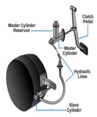
- Movement of the clutch pedal creates hydraulic pressure in the master cylinder, which actuates the slave cylinder.
- The slave cylinder then moves the clutch fork.
Fluid
Coupling:
A Fluid coupling is used for
transmitting power or torque from one to another shaft with the help of oil
(fluid) without mechanical connection of two shafts.

- When the driving shaft with pump impeller is rotated, the oil starts moving from the inner radius to outer radius of the pump impeller by centrifugal action.
- Due to centrifugal action and the speed of impeller, the pressure and kinetic energy of oil at outer radius increases.
- The oil then enters the turbine runner at the outer radius of the runner and flows inwardly to the inner radius of the runner.
- It will exert force and make it run.
- The magnitude of the torque increases with an increases in the speed of driving shaft.
Comments
Post a Comment